• Welcome to the CaliforniaSpecial.com forums! - You are currently viewing the forums as a GUEST. To take advantage of all our site features, please take a moment to join our community! It's fast, simple and absolutely free.

    If you have problems registering or can't log into your account, please contact Admin.

    Please Note: If you are an existing member and your password no longer works, click here to reset it.

1968 Hood-lock holes

joedls

Well-known member
Joined
Mar 12, 2005
Messages
1,980
Location
Lake Forest, CA
Does anyone here have a template and/or measurements for the hood-lock holes in the hood? Any help is appreciated.
 

case12

Well-known member
Joined
Oct 8, 2004
Messages
1,450
Location
Crystal Lake, IL
Here is the blueprint. Not sure if it helps. Casey
 

Attachments

  • TEMPLANTE HOOD PIN LOCATION.pdf
    384.2 KB · Views: 105

PFSlim

Well-known member
Joined
Feb 9, 2004
Messages
1,546
Location
Weatherby Lake, MO
Joe

When we cut ours, we had the original hood available to us. We took measurements 5 or 6 times, then made some really good marks on the hood. We cut a small pilot hole on the topside, then used a hole saw on the bottom side. Lastly, we used a bigger bit to cut the finish hole on the top side.

This was one of the biggest "pucker" times of restoring the car. I remember it well. Not good to do if you are already having a bad day or feel rushed. We even took some breaks while cutting ours just to clear our head. Really turned out nice though.

Good luck.

Paul
 

robert campbell

Well-known member
Joined
Apr 10, 2007
Messages
4,321
Casey,
Interesting blueprint. Wonder what the lines “40 V.” and “15 P.V.” are referenced from?

Joe, My hood is off the car. I could throw a piece of template paper over the front corner on each side and locate the top hole. I put the GT/CS style hood locks in my wife’s 67 Fastback. With the hood painted

But with all the front end work being done on your car, this is what I did to install them on my wife’s car. Takes ambiguity of each car out of the picture:

You had to install a new radiator support and either transferred the hood bumper brackets from your old radiator support (doubtful looking at the damage) to the new radiator support. Anyway, I would mount and adjust the hood. I would then test mount your new lower hood lock brackets on the bumper brackets they attach to. As I remember the hole for the bumper bracket “bumper” was almost dead center to your lower hood lock bracket hole when it is mounted properly. Screw in a 5/16 stud and play with its height until you get it to touch the underside of the hood. Pay attention to the angle it comes up in relation to the hood surface. This will get you very close to where they need to be. You could even turn a point on the 5/16 rod. The angle you drill through the hood should be similar to the angle and relationship of the 5/16 rod to the hood as best you can.

Two inch hole with a long centering bit very carefully from the bottom as I remember.

Rob
 
OP
OP
joedls

joedls

Well-known member
Joined
Mar 12, 2005
Messages
1,980
Location
Lake Forest, CA
Somehow, I don't think I'm going to get the measurments I need off my old hood. :sad:

crash.jpg


Thanks for the drawing, Casey. But I don't think I'm smart enough to get what I need from that drawing.

Anyone else?
 
OP
OP
joedls

joedls

Well-known member
Joined
Mar 12, 2005
Messages
1,980
Location
Lake Forest, CA
Thanks for the info, Rob. But is it really a 2" hole? I kinda remember a big hole on the underside, but I thought the top side of the hood had more like a 1" hole?
 

franklinair

Well-known member
Joined
Mar 1, 2007
Messages
4,744
What about contacting Mike Jewell (somethingspecial)? He did a fantastic job on his concourse C/S.

Neil
 

miller511

Well-known member
Joined
Feb 3, 2004
Messages
567
The Hood Pin Location drawing is interesting. There's not enough info there to build from. I'm assuming all numbers are in inches. Probably need the rest of the car to do measuremnets from.
Looks like-
40 A, and 45 A refer to a reference datum (maybe the top view from firewall?)
20 S.V and 25 S.V. refer to a reference datum (maybe side view from the lower frame?)
15 P.V. and 20 P.V. refer to reference datum (maybe centerline of the hood outward to the passenger side?)
15 W.L. and 20 W.L. refer to reference datum (same as 15 P.V. and 20 P.V?).

Sorry Joe, Didn't intend to tangent ;-) I can measure the '68 hood when I get home tonight.
 
OP
OP
joedls

joedls

Well-known member
Joined
Mar 12, 2005
Messages
1,980
Location
Lake Forest, CA
The Hood Pin Location drawing is interesting. There's not enough info there to build from. I'm assuming all numbers are in inches. Probably need the rest of the car to do measuremnets from.
Looks like-
40 A, and 45 A refer to a reference datum (maybe the top view from firewall?)
20 S.V and 25 S.V. refer to a reference datum (maybe side view from the lower frame?)
15 P.V. and 20 P.V. refer to reference datum (maybe centerline of the hood outward to the passenger side?)
15 W.L. and 20 W.L. refer to reference datum (same as 15 P.V. and 20 P.V?).

Sorry Joe, Didn't intend to tangent ;-) I can measure the '68 hood when I get home tonight.


Thanks, Jeff. Like I said, I'm not smart enough to even figure out what you did from that drawing.
 

robert campbell

Well-known member
Joined
Apr 10, 2007
Messages
4,321
Thanks for the info, Rob. But is it really a 2" hole? I kinda remember a big hole on the underside, but I thought the top side of the hood had more like a 1" hole?

Hole on topside to fit the hood lock shank. About 7/16 diameter. My hood is put away, but the hole on the bottom is 2 & 1/2 diameter in my wife’s car, which I cut. It may not be correct, but someone should ring in. This hole kinda cuts right into one edge of the hood brace. About 3/4 of the hole is in the brace and then it cuts away at the edge of the brace. Someone should have a picture. I would follow my procedure to locate the center of these holes in the hood. As your photo shows it with the damage your car sustained and repairs it will be the best way
 

franklinair

Well-known member
Joined
Mar 1, 2007
Messages
4,744
I tried to bring up the pdf drawing for the hood, but it was too light & unreadable.

Neil
 

miller511

Well-known member
Joined
Feb 3, 2004
Messages
567
Joe,

I took some measurements based on the PDF print that Casey provided. Tried to make sense of the dimensions that are called out.

Looks like the drawing is showing measuring out from the center of the hood at the "V" to the pin. This dimension is 17.61" (15 PV plus 2.61). The tape measure on my hood confirms this as correct.
Now, where the drawing comes up with 40 A plus 4.55 (for 44.55" total) is not clear. I measure 45.55" from the back edge of the hood to pin. A full inch longer. Since the slot on the mating piece runs in the same direction, this dimension is not as critical. But I still don't know where 40 A is as a reference. The more critical dimension is the 17.61 from the center "V" of the hood. I personally would not measure from the outer rolled sheet metal for this dimension as the tolerance on the rolled edge is not real tight. Especially since there are no tolerances on this drawing at all. Although that said, I did measure from the firewall side back rolled edge of the hood to get the 45.55" dimension.

Also, the top hole is .875" diameter and the bottom hole is 2.500" diameter.

Hope this helps.
 

Attachments

  • DSC_0040a.jpg
    DSC_0040a.jpg
    49.4 KB · Views: 46
  • DSC_0041a.jpg
    DSC_0041a.jpg
    112.2 KB · Views: 47
  • DSC_0043a.jpg
    DSC_0043a.jpg
    56.2 KB · Views: 54
  • DSC_0042a.jpg
    DSC_0042a.jpg
    96.9 KB · Views: 48
  • DSC_0044a.jpg
    DSC_0044a.jpg
    56.1 KB · Views: 59
  • DSC_0046a.jpg
    DSC_0046a.jpg
    54.1 KB · Views: 53
  • DSC_0047a.jpg
    DSC_0047a.jpg
    54.8 KB · Views: 56
Last edited:

robert campbell

Well-known member
Joined
Apr 10, 2007
Messages
4,321
Jeff,
Great pictures. Just what the doctor ordered!

Joe,
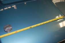
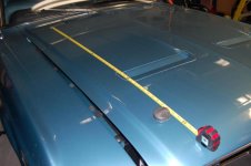
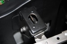
Before you drill any hole in that hood, I would mount it and do what I said a few posts above. I had the hood, but replaced my radiator support in my GT/CS. Took alot of measurements before I removed the radiator support to include the location of the lower brackets and the bracket they bolt to that welds to the radiator support.

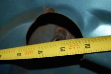
You may find that the hole as per the dimensions in the picture do not locate well with your core support. So I would do a sanity check or locate the bracket on your radiator support based on the hole in your hood, if you drill it first

This is kinda a chance to go back to the actually history of how they did this in 1968 at the factory and how they handled the early prototypes in this one area. This kinda sheds light on how GT/CS cars were built IMO.

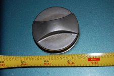
It is pretty obvious that the hoods were not punched for hood locks in the “forming” process and that the hood locks were installed somewhere on the line. Or as I like to think the car was pulled off the line at or near the end into a special area where the taillights, trunk lid, scripts (drilled not punched), side scoops, grill, fog lights, side and trunk stripes, and hood locks were installed. The fog light wiring and taillight harness was in the car already. The rear windows and rear interior panels may have been left out and installed at this point due to the side scoop center stud.

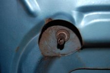
They may have had a special jig that attached to the radiator core support bracket to locate the hole from the bottom up vice drilling down through. But Casey’s blueprints seem to support the drilling from the topside down. But investigation of these holes and known GT/CS cars firmly indicates they were done to a nearly finished and painted car. As we know, the trunk undercoat was even on the car and overspray from painting the exterior was on this undercoat prior to installation of the California Special scripts. A nearly finished car!

I have gotten in some “spirited” discussions with the registrar on the above points. For sure the early cars and the debut cars were hand assembled and never came down the line as a Marti verified dealer ordered GT/CS. At some point in the production the car was ordered as a GT/CS from inception, but IMO the cars were still basically hand assembled at the end. The quarters were drilled and GT/CS scripts installed, the hood was drilled and the hood locks installed and so on. They refined the process as best they could, but these cars were not constructed start to finish as a normal Mustang. Never leaving the line so to speak with all GT/CS attachment points made in the forming process.

No unlike how Shelby cars were built. Oh crap, are we more closely related to a Shelby than we think?? Perish the thought.

Rob
 

CALIF GIRL

Well-known member
Joined
Oct 10, 2004
Messages
643
Joe,

If you need a car to look at/measure against I can bring mine to you.
 
Top