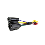
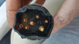
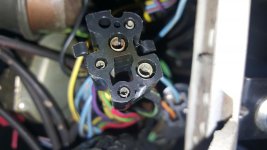
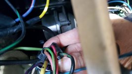
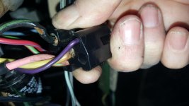
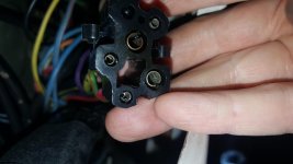
I finally got it through my thick skull that the connector in the pictures was to the ignition switch

So, per page 19-37 and 19-36 (as Arlie said) the yellow wire (21) is hooked directly to the battery. Per page 19-26, the black-green wire (297 and 297A) is connected to 12v when the key is in "accessory" or "run" position. So, from this I think we can infer that this wire provides power to just those accessories that one still wants to be using even when the car is not running (eg radio, heater blower, turn signals, etc... any schematic that has 297 or 297A on it).
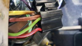
Now, given the pictures, I think there are two possible ways this could be failing.
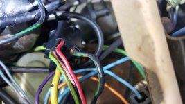
(1) The simplest theory of failure is that the insulation of the black-green wire (which really doesn't appear burned) somehow cracked (old age?) allowing for intermittent shorting to ground near the connector. Anytime this would ground out it would cause very high current in the yellow wire (hence the burn) as well as a sag in voltage going out the resistor wire to the coil (or, now, the relay) which would cause the engine to quit. If this is the case, replacing just the connector (and, possibly the ignition switch that is now likely damaged) should do the trick.
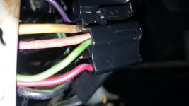
(2) The other explanation is that somewhere in the "accessory powered" circuits there is an intermittent short to ground. This short causes high current in both the black-green and yellow wire which led to both wires having cracked insulation. And, as in #1 above, this also leads to engine quitting when the intermittent short occurs. Figuring this out would be more difficult as it would require finding out just which accessory has the intermittent short.
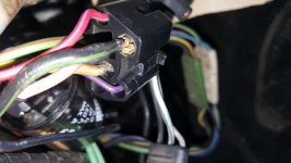
Sheryl, with the idea that #1 is the problem you could just replace the connector/switch and drive it to see if that fixes the problem. If it doesn't or the connector starts to show signs of high current then the short becomes harder to solve.
Aside: none of this explains why the ignitor relay purple wire (which is the control input to the relay) got so hot... that is confusing to me...